4-20mA Explained: Why Industry Measures in Current, Not Volts
TL;DR: 4-20mA is the only industrial signalling standard that has survived every wave of digitalisation, and it survives for one reason. A healthy loop never reads zero. Four milliamps is the bottom of the scale, so nought milliamps cannot be a measurement, it can only be a broken wire, a pulled terminal or a dead transmitter. That single decision is why 4-20mA is still being specified on new build in 2026.
Last updated: 9 September 2026
On this page
Key takeaways
- The 4mA floor is called the live zero. It exists so that no valid reading is ever zero, which makes a cut cable detectable by the receiving card rather than invisible to it.
- Current is identical at every point in a series loop, so cable resistance cannot alter a 4-20mA reading. A 0-10V signal loses part of itself to every ohm of copper.
- NAMUR NE 43 turns the space outside the range into diagnostics: valid measurement clipped to 3.8 to 20.5mA, instrument failure driven below 3.6mA or above 21mA.
- HART rides on the same pair as a small alternating current that averages to zero, so the underlying 4-20mA value is untouched.
- ISA, which owns the standard, states there have been “no technical innovations in this area since 1972”.
- You do not have to replace a working transmitter to get its data into a dashboard. A LoRaWAN IO controller reads the loop and republishes the value.
Why does a 4-20mA loop start at 4mA and not zero?
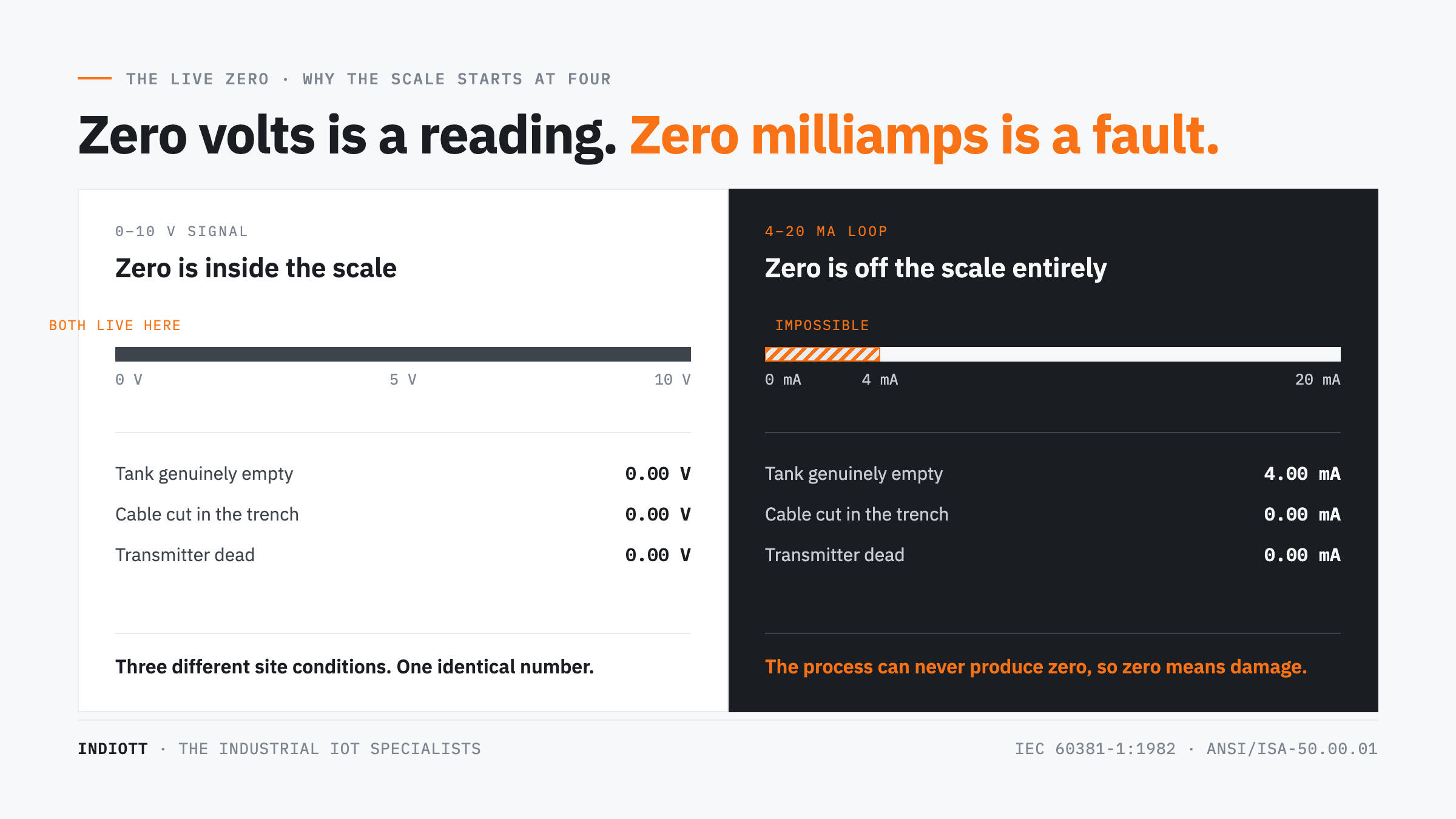
Because zero has to be allowed to mean something. In a 4-20mA loop the bottom of the measuring range is 4mA, so a reading of 0mA sits outside the scale entirely. The receiving card can separate a genuine minimum reading from a severed cable or a dead transmitter. That 4mA floor is the live zero.
Put the alternative next to it and the point becomes obvious. On a 0-10V input, zero volts is a legal reading and also exactly what you measure when the cable is cut. The instrument saying the tank is empty and the instrument lying at the bottom of the tank produce the same number. That ambiguity is the failure mode 4-20mA was designed to delete.
The convention is old and deliberately frozen. The ranges are set out in IEC 60381-1:1982, edition 2.0, with the American equivalent in ANSI/ISA-50.00.01. The committee that owns it is blunt about the pace of change, stating on its ISA50 page that “there have been no technical innovations in this area since 1972”, and that “the annual volume of instruments sold with an ISA-50.1 conforming analog signal is still much larger than all fieldbus instruments combined”.
There is a second prize in the 4mA floor. Four milliamps flowing continuously is enough to run a transmitter’s own electronics, which is why a two-wire 4-20mA transmitter needs no separate power feed. One pair carries supply and measurement at the same time: fewer cores, fewer glands, fewer things to get wrong in a hazardous area.
Why does current beat voltage over a long cable run?
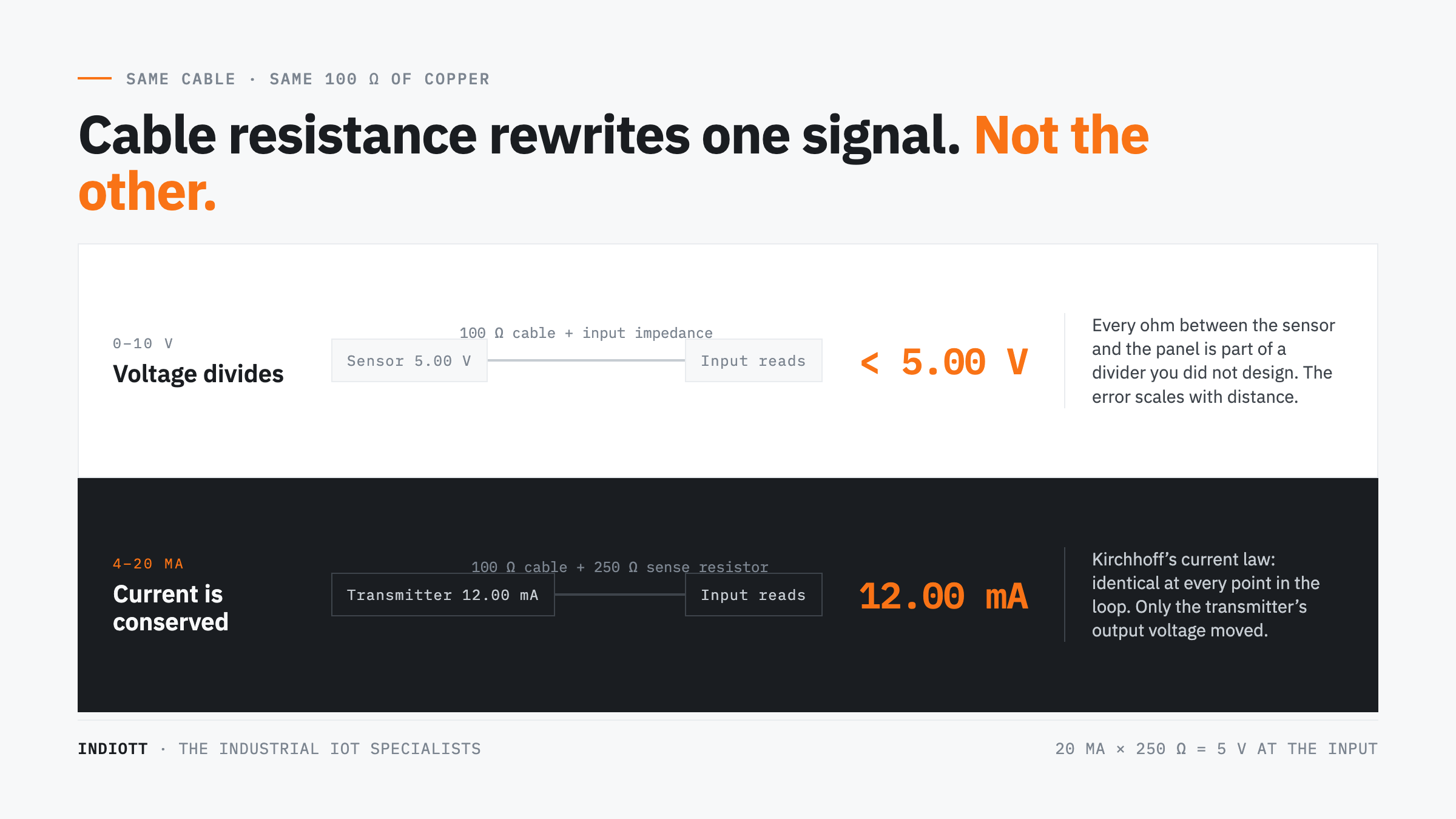
Because current is conserved around a series loop and voltage is not. Kirchhoff’s current law means the current is identical at every point in a 4-20mA circuit, so the resistance of the copper cannot change the number that arrives. A voltage signal, by contrast, gives up part of itself to every ohm between the transmitter and the panel.
The arithmetic is unforgiving. Put 100 ohms of cable resistance in a 4-20mA loop and a 12mA signal still arrives as 12mA; only the voltage the transmitter had to generate changed, and a 24V supply has headroom to spare. Put the same 100 ohms in series with a 0-10V signal and you have built a voltage divider that quietly rescales every reading.
Noise behaves the same way. Induced voltage from a variable speed drive or a poorly bonded cable tray lands on a high-impedance voltage input as signal, because that input cannot tell your millivolts from the drive’s. In a 4-20mA loop the transmitter regulates the current to the value it wants, so the interference is absorbed as a change in its own output voltage, not in the measurement.
At the panel end the current becomes a voltage again across a sense resistor. A 250 ohm resistor is the classic choice: 4mA across it is 1V and 20mA is 5V, landing the range neatly inside a 1-5V input. A lot of field faults live at that resistor.
What does NAMUR NE 43 add to a 4-20mA signal?
NE 43 turns the space either side of the range into a diagnostic channel. The recommendation, published by NAMUR as NE 043, “Standardization of the Signal Level for the Failure Information of Digital Transmitters”, dated 26 July 2021, asks a transmitter to clip valid measurement to a narrower band and to drive the loop outside it when the instrument itself has failed.
- 3.8 to 20.5mA is measurement. Anything the process can legitimately produce lands here.
- 3.6mA or below is a downscale instrument fault.
- 21mA or above is an upscale instrument fault.
- 3.6 to 3.8mA and 20.5 to 21mA are deliberately empty. A compliant transmitter never sits in those gaps, so the receiving system is never left guessing.
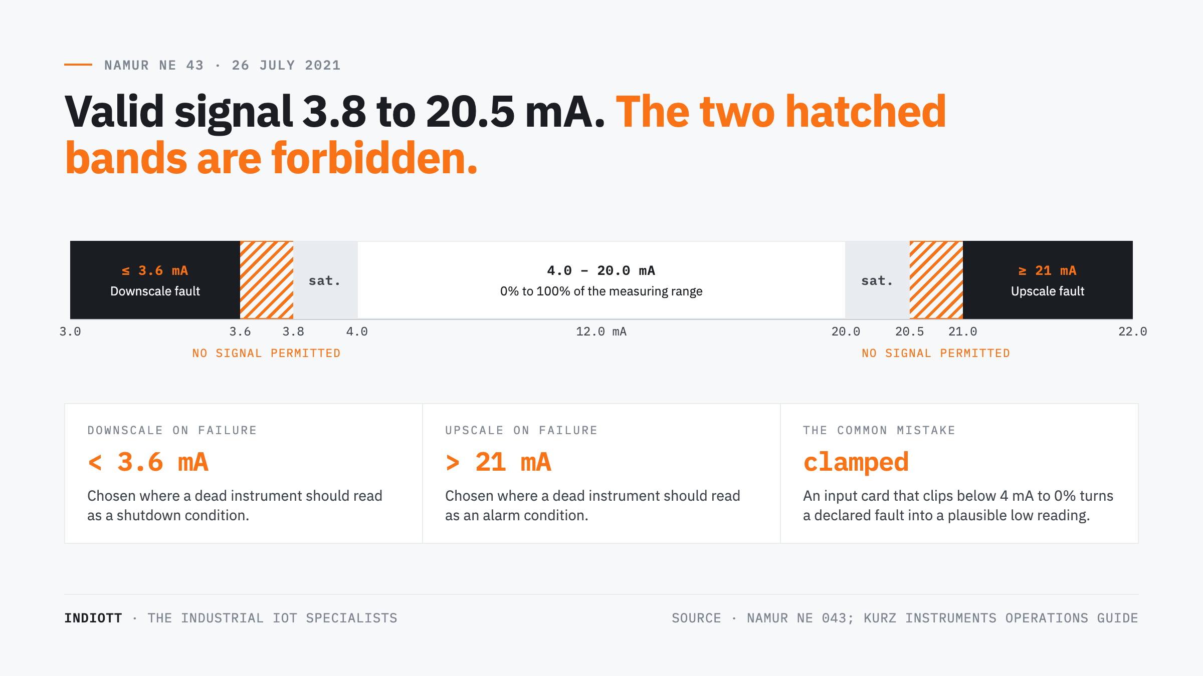
It is a real setting on real instruments, not a paper exercise. The operations guide for Kurz flow meters describes exactly this behaviour: the analogue output is clipped between 3.8 and 20.5mA, and the engineer chooses whether a meter fault drives the output below 3.6mA or above 21mA. Upscale is normal where a failure should look like an alarm condition. Downscale is normal where a failure should look like a shutdown.
Here is the part that costs money. NE 43 only works if the input at the other end honours it. Plenty of cheap analogue cards clamp anything below 4mA to zero percent. Feed a NAMUR-compliant 4-20mA transmitter into an input like that and a failed instrument arrives on the dashboard as a plausible low reading. The diagnostic was sent. Nobody caught it.
How does HART put digital data on the same two wires?
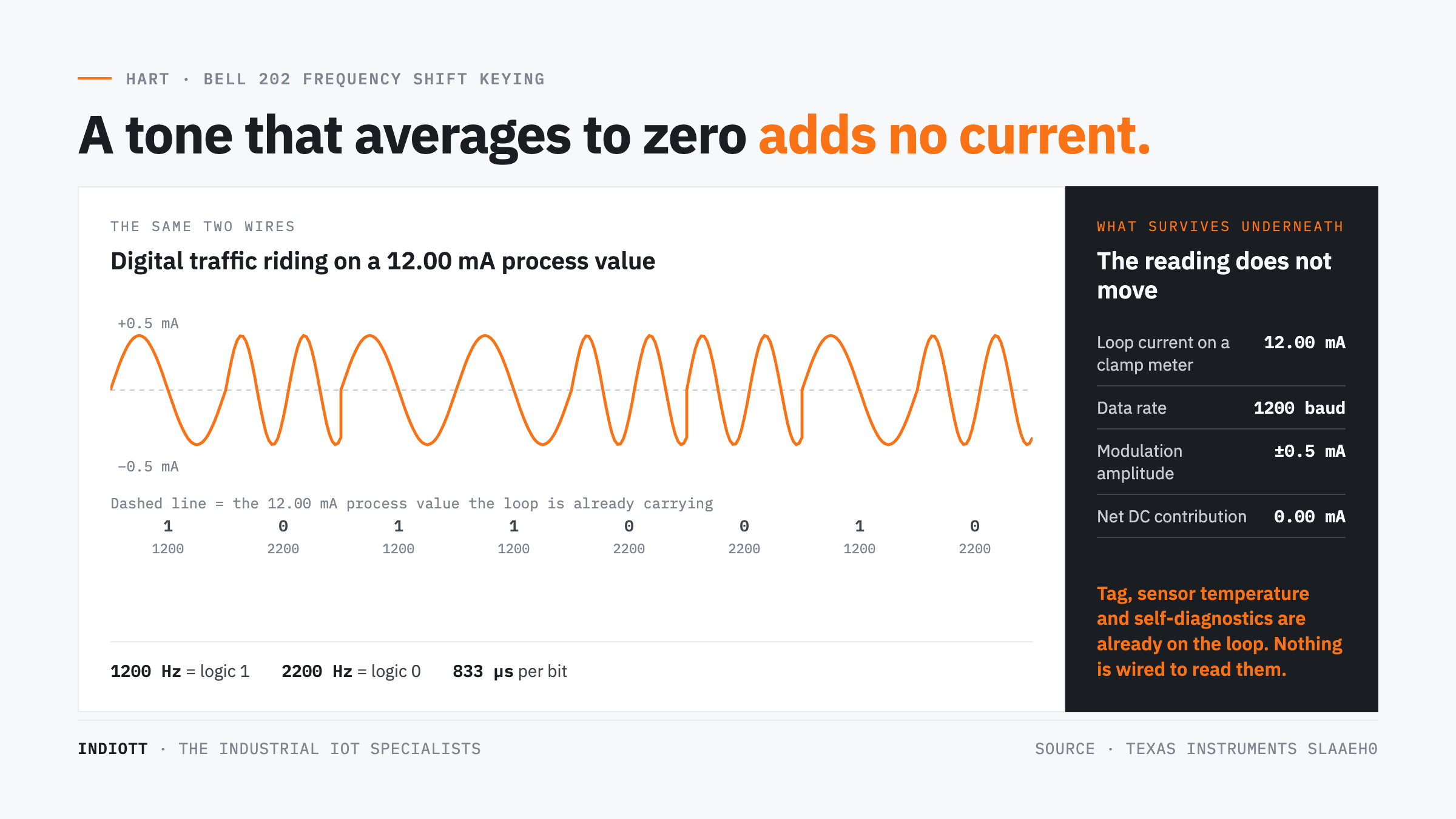
HART superimposes a small alternating current on the existing loop. It uses Bell 202 frequency shift keying, where a 1200Hz tone is a digital one and a 2200Hz tone is a digital zero, both at roughly plus or minus 0.5mA. Because each tone averages to zero over its own bit period, the underlying 4-20mA measurement is not shifted at all.
Texas Instruments sets out the timing in its application note on the protocol: data is sent at 1200 baud, so each bit occupies about 833 microseconds. A conventional milliamp meter clipped onto a loop carrying HART traffic still reads the process value, unchanged, which is precisely why the scheme was adopted rather than a clean-sheet digital bus.
The practical consequence is that many existing 4-20mA instruments already report more than the one number anybody looks at. Device tag, sensor temperature, secondary variables and self-diagnostics sit on the loop unread, because the only thing wired to it is an analogue input card. Before buying new instrumentation, find out what the old instrumentation was already telling you.
Where 4-20mA is the wrong choice
A 4-20mA loop carries one variable, per pair of wires, at analogue resolution, with no timestamp and no address. Wherever you need many variables from one device, or the time an event happened, the loop is the expensive answer and a digital protocol the cheap one.
Accuracy is the other honest caveat, and it belongs to the receiving end as much as the transmitter. On the Milesight UC300 IoT controller the published figures are ±5% on the 4-20mA inputs and ±1% on the 0-10V inputs, both at 12-bit. That is normal for a compact IO controller rather than a laboratory instrument, and it is the number to design around. If a tenth of a percent matters, take the value digitally over Modbus RTU rather than re-digitising a signal that was already digital inside the transmitter.
Twelve bits sounds generous until you see what it is spread across: 4,096 steps over the whole input span, roughly five microamps per step on a 0-20mA input. For a level, a pressure or a flow that is far finer than the process. For four significant figures it is not, and averaging never invents resolution the converter did not have.
Inside a panel, over a metre of wire, 0-10V is sensible and usually cheaper. The case for 4-20mA is distance, noise and the live zero. Take those three away and the argument goes with them.
How do you get a 4-20mA sensor onto LoRaWAN or Modbus?
You do not replace the sensor. You put a controller at the end of the loop that reads the 4-20mA value and republishes it wirelessly. The transmitter, the cable and the calibration all stay exactly as they are, and only the reporting layer is new. This is the cheapest useful thing most sites can do with instrumentation they already own, and it is the core of our SCADA, Modbus and remote IO work.
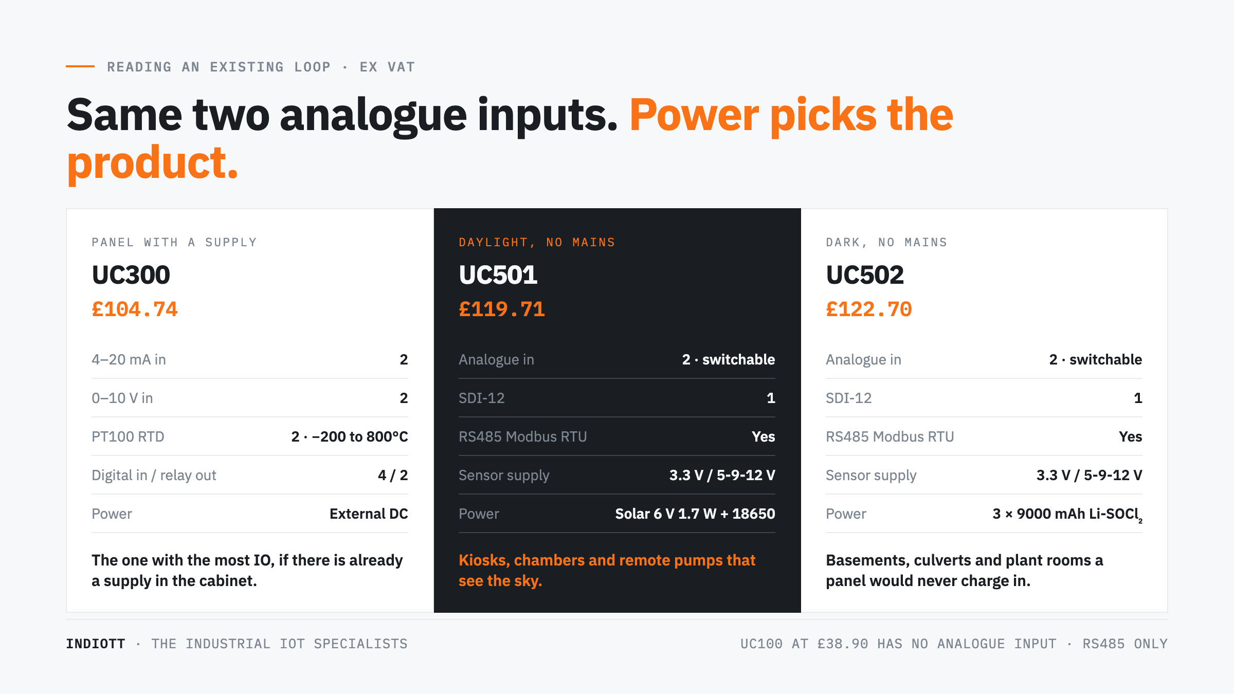
Three controllers cover almost every case we are asked about. All prices are ex VAT.
- Milesight UC300, £104.74. Two 4-20mA inputs plus two 0-10V, four opto-isolated digital inputs, two SPDT relays rated 3A at 30VDC, and two PT100 RTD inputs covering -200°C to 800°C. RS232 and RS485 Modbus RTU, up to 32 registers across 32 devices. Externally powered, so it suits a panel that already has a supply.
- Milesight UC501, £119.71. Two analogue inputs switchable between 4-20mA and 0-10V, SDI-12, RS485 Modbus RTU, M12 connectors, and an embedded 6V 1.7W solar panel charging two 18650 cells. This is the one for a chamber, a kiosk or a remote pump with light but no mains.
- Milesight UC502, £122.70. The same IO set on three 9,000mAh lithium thionyl chloride cells instead of solar, for the underground and indoor positions where a panel would never see the sun.
One specification decides more of these projects than any other: what the controller gives back to the instrument. The UC501 and UC502 supply 3.3V continuously and can switch 5V, 9V or 12V for up to ten minutes before each reading. That wakes many small transmitters on a duty cycle. It will not feed a thirsty one that must stay energised, so check warm-up time and supply current before assuming a battery controller can carry it.
Worth saying plainly, because it comes up weekly: the Milesight UC100 at £38.90 has no analogue input at all. It is an RS485 Modbus RTU to LoRaWAN bridge and nothing else. If your instrument speaks 4-20mA it is the wrong product, however attractive the price. Better to say so here than after the box arrives.
Five checks before you wire a loop into anything new
- Decide who powers the loop. A two-wire transmitter expects the receiving end to supply it; a four-wire transmitter sources current itself. Wiring a source into a source is the commonest way to get nothing at all.
- Add up the compliance voltage. Sense resistor, cable resistance and any barriers, multiplied by 20mA, must sit inside what the loop supply can deliver. Loops that work in the workshop and fail on site usually fail here.
- Confirm sink or source at the input. Compact IO controllers are frequently one or the other, not both.
- Ask whether NE 43 survives the journey. If the transmitter signals a fault at 3.6mA, the new input has to see 3.6mA rather than clamp it to the bottom of the scale.
- Match resolution to the decision, not the datasheet. A tank alarm at 80% does not need four significant figures, and custody transfer is not a job for a 12-bit input.
Frequently asked questions
Can a battery-powered device read a 4-20mA sensor?
Yes, but on a duty cycle. The controller energises the loop for a few seconds, takes the reading and shuts it down again, because 20mA flowing continuously would empty any battery in weeks. That suits level, pressure and temperature. It does not suit a genuinely continuous trace.
What is the maximum cable length for a 4-20mA loop?
There is no fixed figure, because the limit is the voltage budget, not the distance. Total the loop resistance, multiply by 0.02 for the volts needed at full scale, add the transmitter’s minimum operating voltage and check against your supply. Hundreds of metres is routine; kilometres are possible on 24V.
Is 0-10V ever the better choice?
Inside a panel, yes. Over short runs with no serious interference, 0-10V is cheaper to implement and frequently more accurate at the input. On the UC300 the 0-10V inputs are specified at ±1% against ±5% for the current inputs. Once the cable leaves the panel, the live zero and the noise immunity of 4-20mA usually win the argument.
My input is showing 3.6mA. What does that mean?
On a NAMUR NE 43 compliant transmitter, 3.6mA or below is a declared instrument fault, not a low process reading. Something inside the transmitter has failed its own self-check and it is telling you so in the only language the loop has. Treat it as an instrument callout rather than a process event.
Do we have to replace our instruments to get data into a dashboard?
Almost never. A working 4-20mA transmitter with a valid calibration is an asset, not an obstacle. A LoRaWAN IO controller at the panel end keeps the instrument, the wiring and the certificate, and adds the reporting layer that was missing. Rip and replace is the expensive route to the same dashboard.
Where this leaves you
4-20mA is not a legacy signal somebody forgot to retire. It solved the one problem digital systems still handle badly: telling a quiet process apart from a dead instrument. The live zero, the NE 43 fault bands and one pair carrying both power and measurement are why it is still specified on new plant, decades after the standard stopped changing.
What has changed is what sits at the panel end. You no longer need a SCADA project to see a loop. Tell us the transmitter, the distance and whether there is power at the panel, and we will tell you which controller reads it, what it costs and what it will not do. Start with our SCADA, Modbus and remote IO solution, compare hardware in the Milesight IoT controller comparison, and read off-grid monitoring power budgets if the site has no mains. Quotes come back within one working day.
Next step
Get a priced kit list for your site
Answer three quick questions and tell us where to send it. An engineer replies within one working day with the parts, the prices and the lead time.
Rather talk it through? Call 023 9223 3611
Received. An engineer has it.
You will hear back within one working day with the parts, the prices and the lead time. A confirmation is on its way to your inbox.
If it is urgent, call 023 9223 3611.